Wedge Barriers for Beginners
Wiki Article
Wedge Barriers Things To Know Before You Buy

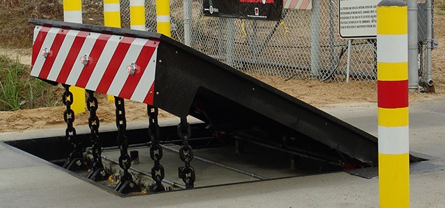
14 and the surface 12 to which the obstacle 10 is protected may be made from concrete - Wedge Barriers. 2, the obstacle 10 is installed to or consists of a support or subframe (e. g., anchor 30 received FIG. 2 )secured underneath the surface area 12. The bather 10 may be bolted to the support or safeguarded to the support by various other mechanical bolts. In the illustrated personification, the obstacle 10 consists of a wedge plate 16, that includes a part that is significantly parallel with the surface 12 when the obstacle 10 is in the withdrawed position. Simply put, cars or individuals might overlook the obstacle 10 when the barrier 10 remains in the withdrawed setting and experience small altitude loved one to the surface area 12 while on the barrier 10. As talked about in detail listed below, when the barrier 10 is in the released placement, the wedge plate 16 is held and sustained in a raised placement by a training device of the obstacle 10. Additionally, the components 18 may be bolted or otherwise mechanically combined to each other. In this way, repair or substitute of several elements 18 may be simplified and structured. That is, repair service or substitute of solitary elements 18 might be done faster, conveniently, and cost properly. FIG. In specific embodiments, the anchor 30 might be a steel framework including plates, beam of lights(e. g., I-beams ), and/or various other structures that are protected within the foundation 14, which may be concrete. At the surface 12, an upper side 28 of the anchor 30 may be at least partially revealed , consequently enabling the add-on of the obstacle 10 to the support 30. g., threaded holes)in one or more light beams or plates of the support 30 may be exposed to the surface 12. In this way, screws 32 or other mechanical fasteners may be used to secure the obstacle 10 to the anchor 30. As the obstacle 10 is installed to the surface area 12 of the foundation 14, collection of particles and various other product underneath the barrier might be minimized, and parts of the bather 10 might not be subjected to listed below quality environments. As suggested by recommendation character 52, the lifting system 50 includes components disposed beneath the wedge plate 16. For instance, the components 52 under the wedge plate 16 might include an electromechanical actuator, a webcam, several web cam surfaces, etc. Furthermore, the lifting device 50 consists of a springtime setting up 54
The springtime rod 58 is coupled to a web cam(e. g., webcam 80 displayed in FIG. 4) of the training device 50. The springs 60 disposed concerning the springtime rod 58 my latest blog post are held in compression by springtime sustains 62, including a repaired springtime support 64. That is, the fixed springtime support 64 is fixed loved one to the structure 14 et cetera of the bather 10.
10 Simple Techniques For Wedge Barriers
g., springtime assistance 65 )may be dealt with to the end of the spring rod 58 to make it possible for compression of the springtimes 60. As the springs 60 are compressed in between the springtime supports 62, the spring setting up 54 produces a pressure acting on the web cam coupled to the spring rod 58 in a direction 66. The remaining force applied to the cam camera deploy release wedge plate 16 may might provided offered an electromechanical actuator 84 or other various other. The spring setting up 54 and the actuator 84(e. g., electromechanical actuator)might run together to equate the webcam and raise the wedge plate 16.
As pointed out over, the spring assembly 54 exerts a consistent force on the camera, while the electromechanical actuator might be managed to apply a variable force on the web cam, thus allowing the training and lowering( i. e., deploying and pulling back )of the wedge plate 16. In particular personifications, the constant force used by the springtime assembly 54 might be adjustable. g., electromechanical actuator) is impaired. As will be valued, the spring assembly 54 might be covered and safeguarded from debris or other elements by a cover plate(e. g., cover plate 68 received FIG. 4) that may be substantially flush with the elevated surface 38 of the foundation 14. As pointed out above, in the released setting, the wedge plate 16 serves to block access or travel beyond the barrier 10. For instance, the obstacle 10(e. g., the wedge plate 16 )may obstruct pedestrians or automobiles from accessing a home or pathway. As reviewed above, the obstacle 10 is affixed to the anchor 30 secured within the foundation 14,
front brackets 71. Consequently, the affiliation settings up 72 might pivot and rotate to enable the like it collapse and expansion of the affiliation settings up 72 throughout retraction and deployment of the bather 10. The affiliation assemblies 72 reason activity of the wedge plate 16 to be restricted. If a vehicle is taking a trip in the direction of the deployed wedge plate 16(e. For copyrightple, in one scenario, the security legs 86 may be expanded duringmaintenance of the barrier 10. When the safety and security legs 86 are deployed, the security legs 86 support the weight of the wedge plate 16 against the surface area 12. Consequently, the training device 50 may be shut off, serviced, gotten rid of, replaced, and so forth. FIG. 5 is partial perspective view of a personification of the surface-mounted wedge-style barrier 10, showing the web cam 80 and the cam surface areas 82 of the training device 50. Specifically, 2 web cam surface areas 82, which are referred to as reduced web cam surface areas 83, are positioned below the web cam 80. The reduced webcam surfaces 83 may be taken care of to the surface area 12 (e. As an copyrightple, the lower web cam surfaces 83 and the installing plate 85 might form a solitary item that is secured to the support 30 by screws or various other mechanical bolts. In addition, 2 webcam surfaces 82, which are described as upper web cam surface areas 87, are placed above the camera 80 and paired to (e. In other embodiments, intervening layers or plates may be positioned between the surface 12 and the reduced camera surface areas 83 and/or the wedge plate 16 and the upper webcam surfaces 87 As pointed out above, the web cam 80 translates along the webcam surface areas 82 when the wedge plate 16 is raised from the retracted placement to the deployed placement. Furthermore, as discussed above, the springtime setting up 54 (see FIG. 3 )may supply a force acting on the webcam 80 in the instructions 102 via spring pole 58, which may lower the force the electromechanical actuator 84 is required to relate to the cam 80 in order to activate and raise the wedge plate 16. 1 )to the deployed setting(see FIG. 4). As revealed, the camera 80 includes track wheels 104(e. g., rollers), which get in touch with and convert along the web cam surface areas 82 throughout operation.
Report this wiki page